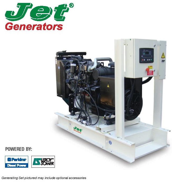
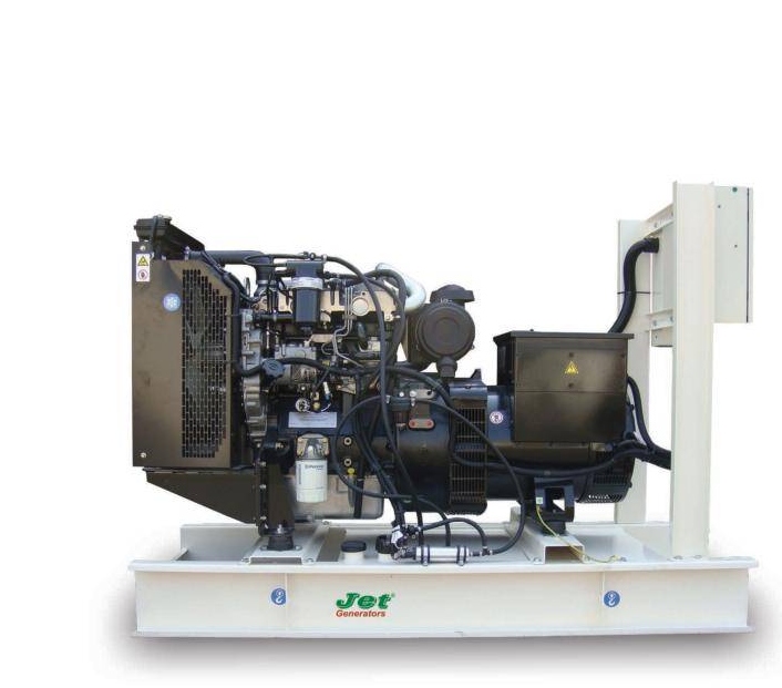
Generator JP60
GENERATING SET MODEL (JP60)
Output RatingsPrimeStandby
380-415 V, 3 ph, 50 Hz, 1500 rpm60 KVA65 KVA
48 KW52 KW
480 V, 3 ph, 60 HZ, 1800 rpm68.1 KVA75 KVA
54.5 KW60 KW
Rating at 0.8 Power Factor
GENERATING SET MODEL (JP60)
Engine MakePerkins
Engine Model1103A-33TG2
Governing TypeMechanical
Number of Cylinders3
Cylinder ArrangementVertical in line
Bore and Stroke mm105 x 127
Displacement / Cubic Capacity litres3.3
Induction SystemTurbocharged
Cycle 4 stroke
System CombustionDirect Injection
Compression Ratio17.25:1
RotationAnti-clockwise, viewed on flywheel
Cooling SystemWater – cooled
Frequency and Engine Speed50Hz & 1500rpm 60HZ & 1800rpm
PrimeStandbyPrimeStandby
Gross Engine Power KW (hp)55 (73.8)60.5 (81.1)63.3 (84.9)69.6 (93.3)
Fuel Consumption @ 50% load L/hr
@ 75% load L/hr
@ 100% load L/hr
7.2
10.4
13.9


15.4
8.8
12.5
16.6


18.2
Total Lubrication System Capacity litres7.97.97.97.9
Total Coolant Capacity (Inc. radiator) litres10.210.210.210.2
Exhaust Temperature: °C557571534564
Radiator Cooling Air Flow (Min): m³/sec1.481.481.851.85
Combustion Air Flow: m³/min3.83.94.74.9
Exhaust Gas Flow: m³/min10.110.411.812.5
Fuel Tank Capacity: litres87878787
DIMENSIONS AND WEIGHT
Length cmWidth cmHeight cmWeight* Kg (wet)
16573132765

STANDARD SPECIFICATIONS

1 – ENGINE

Perkins four stroke heavy duty high-performance industrial type Diesel engine.

2 – ENGINE FILTRATION SYSTEM

  • Cartridge type dry air filter
  • Cartridge type fuel filter
  • Full flow lube oil filter

All filters have replaceable elements

3 – COOLING RADIATOR

Radiator and cooling fan, complete with safety guards, designed to cool the engine at high ambient temperatures.

4 – EXHAUST SYSTEM

Heavy Duty Industrial Exhaust Silencer:
Silencer noise reduction level: 18(dB)
Maximum Allowable Back Pressure: 8.0 50 Hz / 10.0 60Hz

5 – CIRCUIT BREAKER TYPE

ABB 3 pole MCB. (4 pole is optional)

ALTERNATOR DATA
MakeLeroy Somer
ModelLSA42.3VS3
No. of bearings1
Insulation classH
Total Harmonic Contentat no load <3%
– on load < 2%
Wires12
Ingress ProtectionIP23
Excitation SystemSHUNT
Winding Pitch2/3 (wdg 6)
AYR ModelR220
Overspeed2250 min¯¹
Voltage Regulation± 0.5%
Short Circuit Capacity
PMG Excitation System Available as Optional
CONTROL PANEL
MakeDeep Sea
ModelDSE6110
The
DSE6110 is an Auto Start Control Module for single genset applications. It includes a backlit LCD display which clearly shows the status of the engine all the times. This module can either be programmed using the front panel or by using the DSE configuration suite PC software.
Metering and Alarm Indications:
– Generator frequency
– Underspeed, Overspeed
– Generator volts (L-L, L-N)
– Engine oil pressure
– Engine coolant temperature
– Fuel level (warning or shutdown) – optional
– Hours run counter
– Battery volts
– Fail to start/stop
– Emergency stop
– Failed to reach loading voltage/frequency
– Charge fail
– Loss of magnetic pick-up signal – optional
– Low DC voltage
– CAN diagnostics and CAN fail/error

ALL INSPIRED DESIGN TO MEET YOUR NEEDS

RATINGS DEFINITION
Prime Power
These ratings are applicable for supplying continuous electrical power (at variable load) in lieu of commercially purchased power. 10% overload power is available for 1 hour in 12 hours continuous operation.

Standby Power
These ratings are applicable for supplying continuous electrical power (at variable load) in the event of a utility power. No overload is permitted on these ratings.

STANDARD REFERENCE CONDITIONS
Output ratings are presented at 25°C air inlet temperature, barometric pressure 100 kPa, relative humidity 30%. This generating set is designed to operate at high ambient temperatures (up to 55°C), humidity (up to 99%) and higher attitudes. De-ration may apply, please consult your dealer for specific site ratings.
AVAILABLE OPTIONS AND ACCESSORIES
We offer a range of optional features and accessories to tailor our generating sets to meet your power needs.

OPTIONS
* A variety of generating set control and synchronizing panels
* Additional protection alarms and shutdowns
* Water fuel separator
* Water jacket heater
* Battery charger

ACCESSORIES
* Genuine spare parts
* Load banks
* Auxiliary fuel tanks
* Manual & automatic transfer switches

STANDARD SPECIFICATIONS

6. FUEL SYSTEM
On Generating Sets up to 700 KVA, the baseframe design is incorporated with an integral fuel tank with a capacity of approx. 8 hours running at Full Load. The tank is supplied complete with full cap breather, fuel feed and return lines to the Engine and drain plug.

7. ALTERNATOR
7.1 INSULATION SYSTEM
– The insulation system is Class H.
– All windings are impregnated in either a triple dip thermosetting liquid, oil and acid resisting polyester varnish or vaccum pressure impregnated with a special polyester resin.
– Heavy coat of antitracking varnish additional protection against moisture or condensation.

7.2 AUTOMATIC VOLTAGE REGULATOR (AVR)
The fully sealed Automatic Voltage Regulator maintains the Voltage Regulation at 1% Nominal adjustment by means of a trim pot incorporated on the AVR.

7.3 MOTOR STARTING
An overload capacity equivalent to 300% of the Full Load impedance at zero Power Factor can be sustained for 10 seconds, when PMG option is fitted.

8. MOUNTING ARRANGEMENT
8.1 BASE FRAME
The complete Generating Set is mounted as a whole on a heavy duty fabricated steel Baseframe.

8.2 COUPLING
The Engine and Alternator are directly coupled by means of an SAE  flange. The Engine flywheel is flexibly coupled to the. Alternator rotor.

8.3 ANTI-VIBRATION MOUNTING PADS
Anti-Vibration pads are affixed between the Engine/ Alternator feet and the Baseframe thus ensuring complete vibration isolation of the rotating assembly.

8.4 SAFETY GUARDS
The Fan & Fan Drive along with the Battery Charging Alternator are Safety Guard protected for personnel protection.

9. FACTORY TESTS
* The Generating set is load tested before dispatch
* All protective devices control functions and site load conditions are simulated, The generator and its systems are checked before dispatch.

10. EQUIPMENT FINISHING
All mild steel components are fully degreased and painted with powder coated paint to ensure maximum scuff resistance and durability.

11. DOCUMENTATIONS
Operation & Maintenance manual, Circuit wiring diagrams, and Commissioning / Fault Finding Instruction leaflets are accompanied with the Generator.

12. QUALITY STANDARDS
The equipment meets the following standards: BS4999, BS5000, BS5514, IEC 60034, VDEO530, NEMA MG 1 22 and ISO 8528

13. WARRANTY
All of the Generating Sets are covered under a warranty policy for a period of 12 months. Warranty of the equipment is in line with manufacturer’s warranty terms & conditions.

In line with continuous product development, we reserve the right to change specifications without notice.

Generator JP1000
GENERATING SET MODEL (JP1000)
Output RatingsPrimeStandby
400-415 V, 3 ph, 50 Hz, 1500 rpm1000 KVA1100 KVA
800 KW880 KW
Rating at 0.8 Power Factor
GENERATING SET MODEL (JP1000)
Engine MakePerkins
Engine Model4008-30TAG2
Governing ClassISO 8528-1 CLASS G2
Number of Cylinders8
Cylinder ArrangementVertical in line
Bore and Stroke mm160 x 190
Displacement / Cubic Capacity litres30.561
Induction SystemTurbocharged and air to air charge cooled
Cycle 4 stroke
System CombustionDirect Injection
Compression Ratio13:1
RotationAnti-clockwise, viewed from flywheel end
Cooling SystemWater – cooled
Frequency and Engine Speed50Hz & 1500rpm
PrimeStandby
Gross Engine Power KW (hp)901997
Fuel Consumption @ 50% load L/hr
@ 75% load L/hr
@ 100% load L/hr
108
160
213


234
Total Lubrication System Capacity litres153153
Total Coolant Capacity litres140149
Boost Pressure Ratio3.43.86
Exhaust Temperature: °C462473
Radiator Cooling Air Flow (Min): m³/sec19.619.6
Combustion Air Flow: m³/min7784
Exhaust Gas Flow: m³/min185203
Fuel Tank Capacity: litresN/AN/A
DIMENSIONS AND WEIGHT
Length cmWidth cmHeight cmWeight* Kg (wet)
4472202116360

STANDARD SPECIFICATIONS

1 – ENGINE

Perkins four stroke heavy duty high-performance industrial type Diesel engine.

2 – ENGINE FILTRATION SYSTEM

  • Two Cartridge type dry air filter
  • Cartridge type fuel filter
  • Three Full flow lube oil filter

All filters have replaceable elements

3 – TROPICAL COOLING RADIATOR

Radiator and cooling fan, complete with safety guards, designed to cool the engine at high ambient temperatures.

4 – EXHAUST SYSTEM

Heavy Duty Industrial Exhaust Silencer:
Silencer noise reduction level: 10(dB)
Maximum Allowable Back Pressure: 8.0 (kPa)

5 – CIRCUIT BREAKER TYPE

ABB 3 pole ACB / MCCB (supplied disconnected and without cables)*

ALTERNATOR DATA
MakeLeroy Somer
ModelTAL 047D
No. of bearings1
Insulation classH
Total Harmonic Content< 3.5% on load
Wires6
Ingress ProtectionIP23
Excitation SystemSHUNT
Winding Pitch2/3 (n° 6)
AYR ModelR150
Overspeed2250 min¯¹
Voltage Regulation± 1%
Short Circuit Capacity
PMG Excitation System Available as Optional
CONTROL PANEL
MakeDeep Sea
ModelDSE6110
The
DSE6110 is an Auto Start Control Module for single genset applications. It includes a backlit LCD display which clearly shows the status of the engine all the times. This module can either be programmed using the front panel or by using the DSE configuration suite PC software.
Metering and Alarm Indications:
– Generator frequency
– Underspeed, Overspeed
– Generator volts (L-L, L-N)
– Engine oil pressure
– Engine coolant temperature
– Fuel level (warning or shutdown) – optional
– Hours run counter
– Battery volts
– Fail to start/stop
– Emergency stop
– Failed to reach loading voltage/frequency
– Charge fail
– Loss of magnetic pick-up signal – optional
– Low DC voltage
– CAN diagnostics and CAN fail/error

ALL INSPIRED DESIGN TO MEET YOUR NEEDS

RATINGS DEFINITION
Prime Power
These ratings are applicable for supplying continuous electrical power (at variable load) in lieu of commercially purchased power. 10% overload power is available for 1 hour in 12 hours continuous operation.

Standby Power
These ratings are applicable for supplying continuous electrical power (at variable load) in the event of a utility power. No overload is permitted on these ratings.

STANDARD REFERENCE CONDITIONS
Output ratings are presented at 25°C air inlet temperature, barometric pressure 100 kPa, relative humidity 30%. This generating set is designed to operate at high ambient temperatures (up to 55°C), humidity (up to 99%) and higher attitudes. De-ration may apply, please consult your dealer for specific site ratings.
AVAILABLE OPTIONS AND ACCESSORIES
We offer a range of optional features and accessories to tailor our generating sets to meet your power needs.

OPTIONS
* A variety of generating set control and synchronizing panels
* Additional protection alarms and shutdowns
* Water fuel separator
* Water jacket heater
* Battery charger

ACCESSORIES
* Genuine spare parts
* Load banks
* Auxiliary fuel tanks
* Manual & automatic transfer switches

STANDARD SPECIFICATIONS

6. FUEL SYSTEM
On Generating Sets up to 700 KVA, the baseframe design is incorporated with an integral fuel tank with a capacity of approx. 8 hours running at Full Load. The tank is supplied complete with full cap breather, fuel feed and return lines to the Engine and drain plug.

7. ALTERNATOR
7.1 INSULATION SYSTEM
– The insulation system is Class H.
– All windings are impregnated in either a triple dip thermosetting liquid, oil and acid resisting polyester varnish or vaccum pressure impregnated with a special polyester resin.
– Heavy coat of antitracking varnish additional protection against moisture or condensation.

7.2 AUTOMATIC VOLTAGE REGULATOR (AVR)
The fully sealed Automatic Voltage Regulator maintains the Voltage Regulation at 1% Nominal adjustment by means of a trim pot incorporated on the AVR.

7.3 MOTOR STARTING
An overload capacity equivalent to 300% of the Full Load impedance at zero Power Factor can be sustained for 10 seconds, when PMG option is fitted.

8. MOUNTING ARRANGEMENT
8.1 BASE FRAME
The complete Generating Set is mounted as a whole on a heavy duty fabricated steel Baseframe.

8.2 COUPLING
The Engine and Alternator are directly coupled by means of an SAE  flange. The Engine flywheel is flexibly coupled to the. Alternator rotor.

8.3 ANTI-VIBRATION MOUNTING PADS
Anti-Vibration pads are affixed between the Engine/ Alternator feet and the Baseframe thus ensuring complete vibration isolation of the rotating assembly.

8.4 SAFETY GUARDS
The Fan & Fan Drive along with the Battery Charging Alternator are Safety Guard protected for personnel protection.

9. FACTORY TESTS
* The Generating set is load tested before dispatch
* All protective devices control functions and site load conditions are simulated, The generator and its systems are checked before dispatch.

10. EQUIPMENT FINISHING
All mild steel components are fully degreased and painted with powder coated paint to ensure maximum scuff resistance and durability.

11. DOCUMENTATIONS
Operation & Maintenance manual, Circuit wiring diagrams, and Commissioning / Fault Finding Instruction leaflets are accompanied with the Generator.

12. QUALITY STANDARDS
The equipment meets the following standards: BS4999, BS5000, BS5514, IEC 60034, VDEO530, NEMA MG 1 22 and ISO 8528

13. WARRANTY
All of the Generating Sets are covered under a warranty policy for a period of 12 months. Warranty of the equipment is in line with manufacturer’s warranty terms & conditions.

In line with continuous product development, we reserve the right to change specifications without notice.

Generator JP45
GENERATING SET MODEL (JP45)
Output RatingsPrimeStandby
380-415 V, 3 ph, 50 Hz, 1500 rpm45 KVA50 KVA
36 KW40 KW
480 V, 3 ph, 60 HZ, 1800 rpm50 KVA56.3 KW
40 KW45 KW
Rating at 0.8 Power Factor
GENERATING SET MODEL (JP45)
Engine MakePerkins
Engine Model1103A-33TG1
Governing TypeMechanical
Number of Cylinders3
Cylinder ArrangementVertical in line
Bore and Stroke mm105 x 127
Displacement / Cubic Capacity litres3.3
Induction SystemTurbocharged
Cycle 4 stroke
System CombustionDirect Injection
Compression Ratio17.25:1
RotationAnti-clockwise, viewed on flywheel
Cooling SystemWater – cooled
Frequency and Engine Speed50Hz & 1500rpm 60HZ & 1800rpm
PrimeStandbyPrimeStandby
Gross Engine Power KW (hp)42.2 (56.6)46.5 (62.4)50.5 (67.7)55.6 (74.6)
Fuel Consumption @ 50% load L/hr
@ 75% load L/hr
@ 100% load L/hr
5.7
8.2
10.7


12.0
7.1
9.9
12.9


14.3
Total Lubrication System Capacity litres8.38.38.38.3
Total Coolant Capacity (Inc. radiator) litres10.210.210.210.2
Exhaust Temperature: °C492537510551
Radiator Cooling Air Flow (Min): m³/sec0.880.881.171.17
Combustion Air Flow: m³/min2.93.13.73.9
Exhaust Gas Flow: m³/min7.07.78.89.5
Fuel Tank Capacity: litres87878787
DIMENSIONS AND WEIGHT
Length cmWidth cmHeight cmWeight* Kg (wet)
16573132750

STANDARD SPECIFICATIONS

1 – ENGINE

Perkins four stroke heavy duty high-performance industrial type Diesel engine.

2 – ENGINE FILTRATION SYSTEM

  • Cartridge type dry air filter
  • Cartridge type fuel filter
  • Full flow lube oil filter

All filters have replaceable elements

3 – COOLING RADIATOR

Radiator and cooling fan, complete with safety guards, designed to cool the engine at high ambient temperatures.

4 – EXHAUST SYSTEM

Heavy Duty Industrial Exhaust Silencer:
Silencer noise reduction level: 15(dB)
Maximum Allowable Back Pressure: 10.0 @ 50 Hz / 15.0 @ 60Hz

5 – CIRCUIT BREAKER TYPE

ABB 3 pole MCB. (4 pole is optional)

ALTERNATOR DATA
MakeLeroy Somer
ModelLSA42.3M7
No. of bearings1
Insulation classH
Total Harmonic Contentat no load <3%
– on load < 2%
Wires12
Ingress ProtectionIP23
Excitation SystemSHUNT
Winding Pitch2/3 (wdg 6)
AYR ModelR220
Overspeed2250 min¯¹
Voltage Regulation± 0.5%
Short Circuit Capacity
PMG Excitation System Available as Optional
CONTROL PANEL
MakeDeep Sea
ModelDSE6110
The
DSE6110 is an Auto Start Control Module for single genset applications. It includes a backlit LCD display which clearly shows the status of the engine all the times. This module can either be programmed using the front panel or by using the DSE configuration suite PC software.
Metering and Alarm Indications:
– Generator frequency
– Underspeed, Overspeed
– Generator volts (L-L, L-N)
– Engine oil pressure
– Engine coolant temperature
– Fuel level (warning or shutdown) – optional
– Hours run counter
– Battery volts
– Fail to start/stop
– Emergency stop
– Failed to reach loading voltage/frequency
– Charge fail
– Loss of magnetic pick-up signal – optional
– Low DC voltage
– CAN diagnostics and CAN fail/error

ALL INSPIRED DESIGN TO MEET YOUR NEEDS

RATINGS DEFINITION
Prime Power
These ratings are applicable for supplying continuous electrical power (at variable load) in lieu of commercially purchased power. 10% overload power is available for 1 hour in 12 hours continuous operation.

Standby Power
These ratings are applicable for supplying continuous electrical power (at variable load) in the event of a utility power. No overload is permitted on these ratings.

STANDARD REFERENCE CONDITIONS
Output ratings are presented at 25°C air inlet temperature, barometric pressure 100 kPa, relative humidity 30%. This generating set is designed to operate at high ambient temperatures (up to 55°C), humidity (up to 99%) and higher attitudes. De-ration may apply, please consult your dealer for specific site ratings.
AVAILABLE OPTIONS AND ACCESSORIES
We offer a range of optional features and accessories to tailor our generating sets to meet your power needs.

OPTIONS
* A variety of generating set control and synchronizing panels
* Additional protection alarms and shutdowns
* Water fuel separator
* Water jacket heater
* Battery charger

ACCESSORIES
* Genuine spare parts
* Load banks
* Auxiliary fuel tanks
* Manual & automatic transfer switches

STANDARD SPECIFICATIONS

6. FUEL SYSTEM
On Generating Sets up to 700 KVA, the baseframe design is incorporated with an integral fuel tank with a capacity of approx. 8 hours running at Full Load. The tank is supplied complete with full cap breather, fuel feed and return lines to the Engine and drain plug.

7. ALTERNATOR
7.1 INSULATION SYSTEM
– The insulation system is Class H.
– All windings are impregnated in either a triple dip thermosetting liquid, oil and acid resisting polyester varnish or vaccum pressure impregnated with a special polyester resin.
– Heavy coat of antitracking varnish additional protection against moisture or condensation.

7.2 AUTOMATIC VOLTAGE REGULATOR (AVR)
The fully sealed Automatic Voltage Regulator maintains the Voltage Regulation at 1% Nominal adjustment by means of a trim pot incorporated on the AVR.

7.3 MOTOR STARTING
An overload capacity equivalent to 300% of the Full Load impedance at zero Power Factor can be sustained for 10 seconds, when PMG option is fitted.

8. MOUNTING ARRANGEMENT
8.1 BASE FRAME
The complete Generating Set is mounted as a whole on a heavy duty fabricated steel Baseframe.

8.2 COUPLING
The Engine and Alternator are directly coupled by means of an SAE  flange. The Engine flywheel is flexibly coupled to the. Alternator rotor.

8.3 ANTI-VIBRATION MOUNTING PADS
Anti-Vibration pads are affixed between the Engine/ Alternator feet and the Baseframe thus ensuring complete vibration isolation of the rotating assembly.

8.4 SAFETY GUARDS
The Fan & Fan Drive along with the Battery Charging Alternator are Safety Guard protected for personnel protection.

9. FACTORY TESTS
* The Generating set is load tested before dispatch
* All protective devices control functions and site load conditions are simulated, The generator and its systems are checked before dispatch.

10. EQUIPMENT FINISHING
All mild steel components are fully degreased and painted with powder coated paint to ensure maximum scuff resistance and durability.

11. DOCUMENTATIONS
Operation & Maintenance manual, Circuit wiring diagrams, and Commissioning / Fault Finding Instruction leaflets are accompanied with the Generator.

12. QUALITY STANDARDS
The equipment meets the following standards: BS4999, BS5000, BS5514, IEC 60034, VDEO530, NEMA MG 1 22 and ISO 8528

13. WARRANTY
All of the Generating Sets are covered under a warranty policy for a period of 12 months. Warranty of the equipment is in line with manufacturer’s warranty terms & conditions.

In line with continuous product development, we reserve the right to change specifications without notice.

Generator JP500
GENERATING SET MODEL (JP500)
Output RatingsPrimeStandby
400-415 V, 3 ph, 50 Hz, 1500 rpm500 KVA550 KVA
400 KW440 KW
480 V, 3 ph, 60 HZ, 1800 rpm569 KVA624 KVA
455 KW500 KW
Rating at 0.8 Power Factor
GENERATING SET MODEL (JP500)
Engine MakePerkins
Engine Model2506A-E15TAG4
Governing ClassISO 8528-5 G3
Number of Cylinders6
Cylinder ArrangementVertical in line
Bore and Stroke mm137 x 171
Displacement / Cubic Capacity litres15.2
Induction SystemTurbocharged and air to air charge cooled
Cycle 4 stroke
System CombustionDirect Injection
Compression Ratio16:1
RotationAnti-clockwise, viewed on flywheel
Cooling SystemWater – cooled
Frequency and Engine Speed50Hz & 1500rpm 60HZ & 1800rpm
PrimeStandbyPrimeStandby
Gross Engine Power KW (hp)451 (605)495 (664)458 (615)514 (689)
Fuel Consumption @ 50% load L/hr
@ 75% load L/hr
@ 100% load L/hr
53
76
100


1111
53
78
102


116
Total Lubrication System Capacity litres62626262
Total Coolant Capacity litres58585858
Boost Pressure Ratio3.403.603.003.25
Exhaust Temperature: °Cn/a550n/a550
Radiator Cooling Air Flow (Min): m³/sec111113.713.7
Combustion Air Flow: m³/min35.836.634.338
Exhaust Gas Flow: m³/min949896105.3
Fuel Tank Capacity: litres735735735735
DIMENSIONS AND WEIGHT
Length cmWidth cmHeight cmWeight* Kg (wet)
3701152103797

STANDARD SPECIFICATIONS

1 – ENGINE

Perkins four stroke heavy duty high-performance industrial type Diesel engine.

2 – ENGINE FILTRATION SYSTEM

  • Cartridge type dry air filter
  • Two Cartridge type fuel filter
  • Full flow lube oil filter

All filters have replaceable elements

3 – COOLING RADIATOR

Radiator and cooling fan, complete with safety guards, designed to cool the engine at high ambient temperatures.

4 – EXHAUST SYSTEM

Heavy Duty Industrial Exhaust Silencer:
Silencer noise reduction level: 15(dB)
Maximum Allowable Back Pressure: 6.8 (kPa)

5 – CIRCUIT BREAKER TYPE

ABB 3 pole ACB / MCCB (supplied disconnected and without cables)*

ALTERNATOR DATA
MakeLeroy Somer
ModelTAL 047D
No. of bearings1
Insulation classH
Total Harmonic Content< 3.5% on load
Wires6
Ingress ProtectionIP23
Excitation SystemSHUNT
Winding Pitch2/3 (n° 6)
AYR ModelR150
Overspeed2250 min¯¹
Voltage Regulation± 1%
Short Circuit Capacity
PMG Excitation System Available as Optional
CONTROL PANEL
MakeDeep Sea
ModelDSE6110
The
DSE6110 is an Auto Start Control Module for single genset applications. It includes a backlit LCD display which clearly shows the status of the engine all the times. This module can either be programmed using the front panel or by using the DSE configuration suite PC software.
Metering and Alarm Indications:
– Generator frequency
– Underspeed, Overspeed
– Generator volts (L-L, L-N)
– Engine oil pressure
– Engine coolant temperature
– Fuel level (warning or shutdown) – optional
– Hours run counter
– Battery volts
– Fail to start/stop
– Emergency stop
– Failed to reach loading voltage/frequency
– Charge fail
– Loss of magnetic pick-up signal – optional
– Low DC voltage
– CAN diagnostics and CAN fail/error

ALL INSPIRED DESIGN TO MEET YOUR NEEDS

RATINGS DEFINITION
Prime Power
These ratings are applicable for supplying continuous electrical power (at variable load) in lieu of commercially purchased power. 10% overload power is available for 1 hour in 12 hours continuous operation.

Standby Power
These ratings are applicable for supplying continuous electrical power (at variable load) in the event of a utility power. No overload is permitted on these ratings.

STANDARD REFERENCE CONDITIONS
Output ratings are presented at 25°C air inlet temperature, barometric pressure 100 kPa, relative humidity 30%. This generating set is designed to operate at high ambient temperatures (up to 55°C), humidity (up to 99%) and higher attitudes. De-ration may apply, please consult your dealer for specific site ratings.
AVAILABLE OPTIONS AND ACCESSORIES
We offer a range of optional features and accessories to tailor our generating sets to meet your power needs.

OPTIONS
* A variety of generating set control and synchronizing panels
* Additional protection alarms and shutdowns
* Water fuel separator
* Water jacket heater
* Battery charger

ACCESSORIES
* Genuine spare parts
* Load banks
* Auxiliary fuel tanks
* Manual & automatic transfer switches

STANDARD SPECIFICATIONS

6. FUEL SYSTEM
On Generating Sets up to 700 KVA, the baseframe design is incorporated with an integral fuel tank with a capacity of approx. 8 hours running at Full Load. The tank is supplied complete with full cap breather, fuel feed and return lines to the Engine and drain plug.

7. ALTERNATOR
7.1 INSULATION SYSTEM
– The insulation system is Class H.
– All windings are impregnated in either a triple dip thermosetting liquid, oil and acid resisting polyester varnish or vaccum pressure impregnated with a special polyester resin.
– Heavy coat of antitracking varnish additional protection against moisture or condensation.

7.2 AUTOMATIC VOLTAGE REGULATOR (AVR)
The fully sealed Automatic Voltage Regulator maintains the Voltage Regulation at 1% Nominal adjustment by means of a trim pot incorporated on the AVR.

7.3 MOTOR STARTING
An overload capacity equivalent to 300% of the Full Load impedance at zero Power Factor can be sustained for 10 seconds, when PMG option is fitted.

8. MOUNTING ARRANGEMENT
8.1 BASE FRAME
The complete Generating Set is mounted as a whole on a heavy duty fabricated steel Baseframe.

8.2 COUPLING
The Engine and Alternator are directly coupled by means of an SAE  flange. The Engine flywheel is flexibly coupled to the. Alternator rotor.

8.3 ANTI-VIBRATION MOUNTING PADS
Anti-Vibration pads are affixed between the Engine/ Alternator feet and the Baseframe thus ensuring complete vibration isolation of the rotating assembly.

8.4 SAFETY GUARDS
The Fan & Fan Drive along with the Battery Charging Alternator are Safety Guard protected for personnel protection.

9. FACTORY TESTS
* The Generating set is load tested before dispatch
* All protective devices control functions and site load conditions are simulated, The generator and its systems are checked before dispatch.

10. EQUIPMENT FINISHING
All mild steel components are fully degreased and painted with powder coated paint to ensure maximum scuff resistance and durability.

11. DOCUMENTATIONS
Operation & Maintenance manual, Circuit wiring diagrams, and Commissioning / Fault Finding Instruction leaflets are accompanied with the Generator.

12. QUALITY STANDARDS
The equipment meets the following standards: BS4999, BS5000, BS5514, IEC 60034, VDEO530, NEMA MG 1 22 and ISO 8528

13. WARRANTY
All of the Generating Sets are covered under a warranty policy for a period of 12 months. Warranty of the equipment is in line with manufacturer’s warranty terms & conditions.

In line with continuous product development, we reserve the right to change specifications without notice.

Generator JP100
GENERATING SET MODEL (JP100)
Output RatingsPrimeStandby
400-415 V, 3 ph, 50 Hz, 1500 rpm100.0 KVA110.0 KVA
80.0 KW88.0 KW
GENERATING SET MODEL (JP100)
Engine Make & ModelPerkins 1104C-44TAG2
Governing TypeElectronic
Number of Cylinders4
Cylinder ArrangementVertical in line
Bore and Stroke mm105 x 127
Displacement / Cubic Capacity litres4.4
Induction SystemTurbocharged, air to air
Cycle 4 stroke
System CombustionDirect Injection
Compression Ratio18.23:1
RotationAnti-clockwise, viewed on flywheel
Cooling SystemWater – cooled
Frequency and Engine Speed50Hz & 1500rpm
PrimeStandby
Gross Engine Power KW (hp)93.6 (125.1)103 (13.8)
Fuel Consumption @ 50% load L/hr
@ 75% load L/hr
@ 100% load L/hr
11.8
17.1
22.6


24.9
Total Lubrication System Capacity litres8.08.0
Total Coolant Capacity (Inc. radiator) litres12.612.6
Exhaust Temperature: °C514543
Radiator Cooling Air Flow (Min): m³/sec2.762.76
Combustion Air Flow: m³/min6.016.27
Exhaust Gas Flow: m³/min15.216.3
DIMENSIONS AND WEIGHT
Length cmWidth cmHeight cmWeight* Kg (wet)Fuel Tank litres
201721261074152

STANDARD SPECIFICATIONS

1 – ENGINE

Perkins four stroke heavy duty high-performance industrial type Diesel engine.

2 – ENGINE FILTRATION SYSTEM

  • Air filter
  • Fuel filter
  • Full flow lube oil filter

All filters have replaceable elements

3 – COOLING RADIATOR

Radiator and cooling fan, complete with safety guards, designed to cool the engine at high ambient temperatures.

4 – EXHAUST SYSTEM

Heavy Duty Industrial Exhaust Silencer:
Silencer noise reduction level: 13(dB)
Maximum Allowable Back Pressure: 18.0 @ 50 Hz / 15.0 @ 50 Hz

5 – CIRCUIT BREAKER TYPE

ABB 3 pole MCCB. (4 pole is optional)

ALTERNATOR DATA
MakeLeroy Somer
ModelTAL 044D
No. of bearings1
Insulation classH
Total Harmonic Contentat no load < 2%
– on load < 5%
Ingress ProtectionIP23
Excitation SystemSHUNT
Winding Pitch2/3
AVR ModelR120
Overspeed2250 min¯¹
Voltage Regulation± 1%
Short Circuit Capacity
AREP or PMG Excitation System Available as Optional
CONTROL PANEL
MakeDeep Sea
ModelDSE6120
The DSE6120 is an Auto Mans (Utility) Failure Control Module suitable for a wide variety of single diesel or gas genset applications. It includes a backlit LCD display which clearly shows the status of the engine all the times. This module can either be programmed using the front panel or by using the DSE configuration suite PC software.
Metering and Alarm Indications:
– Generator frequency
– Underspeed, Overspeed
– Generator volts (L-L, L-N)
– Engine oil pressure
– Engine coolant temperature
– Fuel level (warning or shutdown) – optional
– Hours run counter
– Battery volts
– Fail to start/stop
– Emergency stop
– Failed to reach loading voltage/frequency
– Charge fail
– Loss of magnetic pick-up signal – optional
– Low DC voltage
– CAN diagnostics and CAN fail/error

ALL INSPIRED DESIGN TO MEET YOUR NEEDS

RATINGS DEFINITION
Prime Power
These ratings are applicable for supplying continuous electrical power (at variable load) in lieu of commercially purchased power. 10% overload power is available for 1 hour in 12 hours continuous operation.

Standby Power
These ratings are applicable for supplying continuous electrical power (at variable load) in the event of a utility power. No overload is permitted on these ratings.

STANDARD REFERENCE CONDITIONS
Output ratings are presented at 25°C air inlet temperature, barometric pressure 100 kPa, relative humidity 30%. This generating set is designed to operate at high ambient temperatures (up to 55°C), humidity (up to 99%) and higher attitudes. De-ration may apply, please consult your dealer for specific site ratings.
AVAILABLE OPTIONS AND ACCESSORIES
We offer a range of optional features and accessories to tailor our generating sets to meet your power needs.

OPTIONS
* A variety of generating set control and synchronizing panels
* Additional protection alarms and shutdowns
* Water fuel separator
* Water jacket heater
* Battery charger

ACCESSORIES
* Genuine spare parts
* Load banks
* Auxiliary fuel tanks
* Manual & automatic transfer switches

STANDARD SPECIFICATIONS

6. FUEL SYSTEM
On Generating Sets up to 650 KVA, the baseframe design is incorporated with an integral fuel tank with a capacity of approx. 8 hours running at Full Load. The tank is supplied complete with full cap breather, fuel feed and return lines to the Engine and drain plug.

7. ALTERNATOR
7.1 INSULATION SYSTEM
– The insulation system is Class H.
– All windings are impregnated in either a triple dip thermosetting liquid, oil and acid resisting polyester varnish or vaccum pressure impregnated with a special polyester resin.
– Heavy coat of antitracking varnish additional protection against moisture or condensation.

7.2 AUTOMATIC VOLTAGE REGULATOR (AVR)
The fully sealed Automatic Voltage Regulator maintains the Voltage Regulation at 1% Nominal adjustment by means of a trim pot incorporated on the AVR.

7.3 MOTOR STARTING
An overload capacity equivalent to 300% of the Full Load impedance at zero Power Factor can be sustained for 10 seconds, when PMG option is fitted.

8. MOUNTING ARRANGEMENT
8.1 BASE FRAME
The complete Generating Set is mounted as a whole on a heavy duty fabricated steel Baseframe.

8.2 COUPLING
The Engine and Alternator are directly coupled by means of an SAE  flange. The Engine flywheel is flexibly coupled to the. Alternator rotor.

8.3 ANTI-VIBRATION MOUNTING PADS
Anti-Vibration pads are affixed between the Engine/ Alternator feet and the Baseframe thus ensuring complete vibration isolation of the rotating assembly.

8.4 SAFETY GUARDS
The Fan & Fan Drive along with the Battery Charging Alternator are Safety Guard protected for personnel protection.

9. FACTORY TESTS
* The Generating set is load tested before dispatch
* All protective devices control functions and site load conditions are simulated, The generator and its systems are checked before dispatch.

10. EQUIPMENT FINISHING
All mild steel components are fully degreased and painted with powder coated paint to ensure maximum scuff resistance and durability.

11. DOCUMENTATIONS
Operation & Maintenance manual, Circuit wiring diagrams, and Commissioning / Fault Finding Instruction leaflets are accompanied with the Generator.

12. QUALITY STANDARDS
The equipment meets the following standards: BS4999, BS5000, BS5514, IEC 60034, VDEO530, NEMA MG 1 22 and ISO 8528

13. WARRANTY
All of the Generating Sets are covered under a warranty policy for a period of 12 months. Warranty of the equipment is in line with manufacturer’s warranty terms & conditions.

In line with continuous product development, we reserve the right to change specifications without notice.

Generator JP80
GENERATING SET MODEL (JP80)
Output RatingsPrimeStandby
380-415 V, 3 ph, 50 Hz, 1500 rpm80 KVA88 KVA
64 KW70.4 KW
480 V, 3 ph, 60 HZ, 1800 rpm90 KVA100 KVA
72 KW80 KW
Rating at 0.8 Power Factor
GENERATING SET MODEL (JP80)
Engine MakePerkins
Engine Model1104A-44TG2
Governing TypeMechanical
Number of Cylinders3
Cylinder ArrangementVertical in line
Bore and Stroke mm105 x 127
Displacement / Cubic Capacity litres4.4
Induction SystemTurbocharged
Cycle 4 stroke
System CombustionDirect Injection
Compression Ratio17.25:1
RotationAnti-clockwise, viewed on flywheel
Cooling SystemWater – cooled
Frequency and Engine Speed50Hz & 1500rpm 60HZ & 1800rpm
PrimeStandbyPrimeStandby
Gross Engine Power KW (hp)73.4 (98.4)80.7 (108.2)84.5 (113.3)93.0 (124.7)
Fuel Consumption @ 50% load L/hr
@ 75% load L/hr
@ 100% load L/hr
9.7
14
18.7


20.5
11.9
16.9
22.3


24.4
Total Lubrication System Capacity litres8888
Total Coolant Capacity (Inc. radiator) litres13.013.013.013.0
Exhaust Temperature: °C555580535560
Radiator Cooling Air Flow (Min): m³/sec1.481.481.851.85
Combustion Air Flow: m³/min4.85.146.26.5
Exhaust Gas Flow: m³/min12.513.31515.85
Fuel Tank Capacity: litres109109109109
DIMENSIONS AND WEIGHT
Length cmWidth cmHeight cmWeight* Kg (wet)
202731241010

STANDARD SPECIFICATIONS

1 – ENGINE

Perkins four stroke heavy duty high-performance industrial type Diesel engine.

2 – ENGINE FILTRATION SYSTEM

  • Cartridge type dry air filter
  • Cartridge type fuel filter
  • Full flow lube oil filter

All filters have replaceable elements

3 – COOLING RADIATOR

Radiator and cooling fan, complete with safety guards, designed to cool the engine at high ambient temperatures.

4 – EXHAUST SYSTEM

Heavy Duty Industrial Exhaust Silencer:
Silencer noise reduction level: 13(dB)
Maximum Allowable Back Pressure: 10.0 50 Hz / 15.0 60Hz

5 – CIRCUIT BREAKER TYPE

ABB 3 pole MCCB. (4 pole is optional)

ALTERNATOR DATA
MakeLeroy Somer
ModelLSA43.2LB / LSA44.3S3
No. of bearings1
Insulation classH
Total Harmonic Content< 2%
Wires12
Ingress ProtectionIP23
Excitation SystemSHUNT
Winding Pitch2/3 (bob 6)
AYR ModelR250
Overspeed2250 min¯¹
Voltage Regulation± 0.5%
Short Circuit Capacity
PMG Excitation System Available as Optional
CONTROL PANEL
MakeDeep Sea
ModelDSE6110
The
DSE6110 is an Auto Start Control Module for single genset applications. It includes a backlit LCD display which clearly shows the status of the engine all the times. This module can either be programmed using the front panel or by using the DSE configuration suite PC software.
Metering and Alarm Indications:
– Generator frequency
– Underspeed, Overspeed
– Generator volts (L-L, L-N)
– Engine oil pressure
– Engine coolant temperature
– Fuel level (warning or shutdown) – optional
– Hours run counter
– Battery volts
– Fail to start/stop
– Emergency stop
– Failed to reach loading voltage/frequency
– Charge fail
– Loss of magnetic pick-up signal – optional
– Low DC voltage
– CAN diagnostics and CAN fail/error

ALL INSPIRED DESIGN TO MEET YOUR NEEDS

RATINGS DEFINITION
Prime Power
These ratings are applicable for supplying continuous electrical power (at variable load) in lieu of commercially purchased power. 10% overload power is available for 1 hour in 12 hours continuous operation.

Standby Power
These ratings are applicable for supplying continuous electrical power (at variable load) in the event of a utility power. No overload is permitted on these ratings.

STANDARD REFERENCE CONDITIONS
Output ratings are presented at 25°C air inlet temperature, barometric pressure 100 kPa, relative humidity 30%. This generating set is designed to operate at high ambient temperatures (up to 55°C), humidity (up to 99%) and higher attitudes. De-ration may apply, please consult your dealer for specific site ratings.
AVAILABLE OPTIONS AND ACCESSORIES
We offer a range of optional features and accessories to tailor our generating sets to meet your power needs.

OPTIONS
* A variety of generating set control and synchronizing panels
* Additional protection alarms and shutdowns
* Water fuel separator
* Water jacket heater
* Battery charger

ACCESSORIES
* Genuine spare parts
* Load banks
* Auxiliary fuel tanks
* Manual & automatic transfer switches

STANDARD SPECIFICATIONS

6. FUEL SYSTEM
On Generating Sets up to 700 KVA, the baseframe design is incorporated with an integral fuel tank with a capacity of approx. 8 hours running at Full Load. The tank is supplied complete with full cap breather, fuel feed and return lines to the Engine and drain plug.

7. ALTERNATOR
7.1 INSULATION SYSTEM
– The insulation system is Class H.
– All windings are impregnated in either a triple dip thermosetting liquid, oil and acid resisting polyester varnish or vaccum pressure impregnated with a special polyester resin.
– Heavy coat of antitracking varnish additional protection against moisture or condensation.

7.2 AUTOMATIC VOLTAGE REGULATOR (AVR)
The fully sealed Automatic Voltage Regulator maintains the Voltage Regulation at 1% Nominal adjustment by means of a trim pot incorporated on the AVR.

7.3 MOTOR STARTING
An overload capacity equivalent to 300% of the Full Load impedance at zero Power Factor can be sustained for 10 seconds, when PMG option is fitted.

8. MOUNTING ARRANGEMENT
8.1 BASE FRAME
The complete Generating Set is mounted as a whole on a heavy duty fabricated steel Baseframe.

8.2 COUPLING
The Engine and Alternator are directly coupled by means of an SAE  flange. The Engine flywheel is flexibly coupled to the. Alternator rotor.

8.3 ANTI-VIBRATION MOUNTING PADS
Anti-Vibration pads are affixed between the Engine/ Alternator feet and the Baseframe thus ensuring complete vibration isolation of the rotating assembly.

8.4 SAFETY GUARDS
The Fan & Fan Drive along with the Battery Charging Alternator are Safety Guard protected for personnel protection.

9. FACTORY TESTS
* The Generating set is load tested before dispatch
* All protective devices control functions and site load conditions are simulated, The generator and its systems are checked before dispatch.

10. EQUIPMENT FINISHING
All mild steel components are fully degreased and painted with powder coated paint to ensure maximum scuff resistance and durability.

11. DOCUMENTATIONS
Operation & Maintenance manual, Circuit wiring diagrams, and Commissioning / Fault Finding Instruction leaflets are accompanied with the Generator.

12. QUALITY STANDARDS
The equipment meets the following standards: BS4999, BS5000, BS5514, IEC 60034, VDEO530, NEMA MG 1 22 and ISO 8528

13. WARRANTY
All of the Generating Sets are covered under a warranty policy for a period of 12 months. Warranty of the equipment is in line with manufacturer’s warranty terms & conditions.

In line with continuous product development, we reserve the right to change specifications without notice.

Generator JP30
GENERATING SET MODEL (JP30)
Output RatingsPrimeStandby
380-415 V, 3 ph, 50 Hz, 1500 rpm30 KVA33 KVA
24 KW26.4 KW
480 V, 3 ph, 60 HZ, 1800 rpm33.8 KVA37.5 KW
27 KW30 KW
Rating at 0.8 Power Factor
GENERATING SET MODEL (JP30)
Engine MakePerkins
Engine Model1103A-33G
Governing TypeMechanical
Number of Cylinders3
Cylinder ArrangementVertical in line
Bore and Stroke mm105 x 127
Displacement / Cubic Capacity litres3.3
Induction SystemNaturally Aspirated
Cycle 4 stroke
System CombustionDirect Injection
Compression Ratio19.25:1
RotationAnti-clockwise, viewed on flywheel
Cooling SystemWater – cooled
Frequency and Engine Speed50Hz & 1500rpm 60HZ & 1800rpm
PrimeStandbyPrimeStandby
Gross Engine Power KW (hp)28.2 (37.8)31.0 (41.6)33.2 (44.5)36.5 (48.9)
Fuel Consumption @ 50% load L/hr
@ 75% load L/hr
@ 100% load L/hr
3.9
5.4
7.1


7.9
4.9
6.6
8.6


9.5
Total Lubrication System Capacity litres7.97.97.97.9
Total Coolant Capacity (Inc. radiator) litres10.210.210.210.2
Exhaust Temperature: °C500520520530
Radiator Cooling Air Flow (Min): m³/sec0.880.881.171.17
Combustion Air Flow: m³/min2.162.152.62.57
Exhaust Gas Flow: m³/min5.75.86.46.6
Fuel Tank Capacity: litres87878787
DIMENSIONS AND WEIGHT
Length cmWidth cmHeight cmWeight* Kg (wet)
16573132700

STANDARD SPECIFICATIONS

1 – ENGINE

Perkins four stroke heavy duty high-performance industrial type Diesel engine.

2 – ENGINE FILTRATION SYSTEM

  • Cartridge type dry air filter
  • Cartridge type fuel filter
  • Full flow lube oil filter

All filters have replaceable elements

3 – COOLING RADIATOR

Radiator and cooling fan, complete with safety guards, designed to cool the engine at high ambient temperatures.

4 – EXHAUST SYSTEM

Heavy Duty Industrial Exhaust Silencer:
Silencer noise reduction level: 18(dB)
Maximum Allowable Back Pressure: 8.0 50 Hz / 10.0 60Hz

5 – CIRCUIT BREAKER TYPE

ABB 3 pole MCB. (4 pole is optional)

ALTERNATOR DATA
MakeLeroy Somer
ModelLSA42.3VS3
No. of bearings1
Insulation classH
Total Harmonic Contentat no load <3%
– on load < 2%
Wires12
Ingress ProtectionIP23
Excitation SystemSHUNT
Winding Pitch2/3 (wdg 6)
AYR ModelR220
Overspeed2250 min¯¹
Voltage Regulation± 0.5%
Short Circuit Capacity
PMG Excitation System Available as Optional
CONTROL PANEL
MakeDeep Sea
ModelDSE6110
The
DSE6110 is an Auto Start Control Module for single genset applications. It includes a backlit LCD display which clearly shows the status of the engine all the times. This module can either be programmed using the front panel or by using the DSE configuration suite PC software.
Metering and Alarm Indications:
– Generator frequency
– Underspeed, Overspeed
– Generator volts (L-L, L-N)
– Engine oil pressure
– Engine coolant temperature
– Fuel level (warning or shutdown) – optional
– Hours run counter
– Battery volts
– Fail to start/stop
– Emergency stop
– Failed to reach loading voltage/frequency
– Charge fail
– Loss of magnetic pick-up signal – optional
– Low DC voltage
– CAN diagnostics and CAN fail/error

ALL INSPIRED DESIGN TO MEET YOUR NEEDS

RATINGS DEFINITION
Prime Power
These ratings are applicable for supplying continuous electrical power (at variable load) in lieu of commercially purchased power. 10% overload power is available for 1 hour in 12 hours continuous operation.

Standby Power
These ratings are applicable for supplying continuous electrical power (at variable load) in the event of a utility power. No overload is permitted on these ratings.

STANDARD REFERENCE CONDITIONS
Output ratings are presented at 25°C air inlet temperature, barometric pressure 100 kPa, relative humidity 30%. This generating set is designed to operate at high ambient temperatures (up to 55°C), humidity (up to 99%) and higher attitudes. De-ration may apply, please consult your dealer for specific site ratings.
AVAILABLE OPTIONS AND ACCESSORIES
We offer a range of optional features and accessories to tailor our generating sets to meet your power needs.

OPTIONS
* A variety of generating set control and synchronizing panels
* Additional protection alarms and shutdowns
* Water fuel separator
* Water jacket heater
* Battery charger

ACCESSORIES
* Genuine spare parts
* Load banks
* Auxiliary fuel tanks
* Manual & automatic transfer switches

STANDARD SPECIFICATIONS

6. FUEL SYSTEM
On Generating Sets up to 700 KVA, the baseframe design is incorporated with an integral fuel tank with a capacity of approx. 8 hours running at Full Load. The tank is supplied complete with full cap breather, fuel feed and return lines to the Engine and drain plug.

7. ALTERNATOR
7.1 INSULATION SYSTEM
– The insulation system is Class H.
– All windings are impregnated in either a triple dip thermosetting liquid, oil and acid resisting polyester varnish or vaccum pressure impregnated with a special polyester resin.
– Heavy coat of antitracking varnish additional protection against moisture or condensation.

7.2 AUTOMATIC VOLTAGE REGULATOR (AVR)
The fully sealed Automatic Voltage Regulator maintains the Voltage Regulation at 1% Nominal adjustment by means of a trim pot incorporated on the AVR.

7.3 MOTOR STARTING
An overload capacity equivalent to 300% of the Full Load impedance at zero Power Factor can be sustained for 10 seconds, when PMG option is fitted.

8. MOUNTING ARRANGEMENT
8.1 BASE FRAME
The complete Generating Set is mounted as a whole on a heavy duty fabricated steel Baseframe.

8.2 COUPLING
The Engine and Alternator are directly coupled by means of an SAE  flange. The Engine flywheel is flexibly coupled to the. Alternator rotor.

8.3 ANTI-VIBRATION MOUNTING PADS
Anti-Vibration pads are affixed between the Engine/ Alternator feet and the Baseframe thus ensuring complete vibration isolation of the rotating assembly.

8.4 SAFETY GUARDS
The Fan & Fan Drive along with the Battery Charging Alternator are Safety Guard protected for personnel protection.

9. FACTORY TESTS
* The Generating set is load tested before dispatch
* All protective devices control functions and site load conditions are simulated, The generator and its systems are checked before dispatch.

10. EQUIPMENT FINISHING
All mild steel components are fully degreased and painted with powder coated paint to ensure maximum scuff resistance and durability.

11. DOCUMENTATIONS
Operation & Maintenance manual, Circuit wiring diagrams, and Commissioning / Fault Finding Instruction leaflets are accompanied with the Generator.

12. QUALITY STANDARDS
The equipment meets the following standards: BS4999, BS5000, BS5514, IEC 60034, VDEO530, NEMA MG 1 22 and ISO 8528

13. WARRANTY
All of the Generating Sets are covered under a warranty policy for a period of 12 months. Warranty of the equipment is in line with manufacturer’s warranty terms & conditions.

In line with continuous product development, we reserve the right to change specifications without notice.

Generator JP20
GENERATING SET MODEL (JP20)
Output RatingsPrimeStandby
380-415 V, 3 ph, 50 Hz, 1500 rpm20 KVA22 KVA
16 KW17.6 KW
Rating at 0.8 Power Factor
GENERATING SET MODEL (JP20)
Engine MakePerkins
Engine Model404A-22G
Governing TypeMechanical
Number of Cylinders4
Cylinder ArrangementVertical in line
Bore and Stroke mm84 x 100
Displacement / Cubic Capacity litres2.216
Induction SystemNaturally Aspirated
Cycle 4 stroke
System CombustionIndirect Injection
Compression Ratio23.3:1
RotationAnti-clockwise, viewed on flywheel
Cooling SystemWater – cooled
Frequency and Engine Speed50Hz & 1500rpm
PrimeStandby
Gross Engine Power KW (hp)18.7 (25.1)20.6 (27)
Fuel Consumption @ 50% load L/hr
@ 75% load L/hr
@ 100% load L/hr
2.9
4.0
5.3


6.1
Total Lubrication System Capacity litres10.610.6
Total Coolant Capacity (Inc. radiator) litres7.07.0
Exhaust Temperature: °C445505
Radiator Cooling Air Flow (Min): m³/sec0.490.49
Combustion Air Flow: m³/min1.451.45
Exhaust Gas Flow: m³/min3.643.94
Fuel Tank Capacity: litres5050
DIMENSIONS AND WEIGHT
Length cmWidth cmHeight cmWeight* Kg (wet)
12752142.7475

STANDARD SPECIFICATIONS

1 – ENGINE

Perkins four stroke heavy duty high-performance industrial type Diesel engine.

2 – ENGINE FILTRATION SYSTEM

  • Air filter
  • Fuel filter
  • Full flow lube oil filter

All filters have replaceable elements

3 – COOLING RADIATOR

Radiator and cooling fan, complete with safety guards, designed to cool the engine at high ambient temperatures.

4 – EXHAUST SYSTEM

Heavy Duty Industrial Exhaust Silencer:
Silencer noise reduction level: 20(dB)
Maximum Allowable Back Pressure: 10.2 (kPa)

5 – CIRCUIT BREAKER TYPE

ABB 3 pole MCB. (4 pole is optional)

ALTERNATOR DATA
MakeLeroy Somer
ModelTAL040F
No. of bearings1
Insulation classH
Total Harmonic Contentat no load <3.5%
– on load < 5%
Wires12
Ingress ProtectionIP23
Excitation SystemSHUNT
Winding Pitch2/3 (wdg 3)
AYR ModelR120
Overspeed2250 min¯¹
Voltage Regulation± 1%
Short Circuit Capacity
PMG Excitation System Available as Optional
CONTROL PANEL
MakeDeep Sea
ModelDSE6110
The
DSE6110 is an Auto Start Control Module for single genset applications. It includes a backlit LCD display which clearly shows the status of the engine all the times. This module can either be programmed using the front panel or by using the DSE configuration suite PC software.
Metering and Alarm Indications:
– Generator frequency
– Underspeed, Overspeed
– Generator volts (L-L, L-N)
– Engine oil pressure
– Engine coolant temperature
– Fuel level (warning or shutdown) – optional
– Hours run counter
– Battery volts
– Fail to start/stop
– Emergency stop
– Failed to reach loading voltage/frequency
– Charge fail
– Loss of magnetic pick-up signal – optional
– Low DC voltage
– CAN diagnostics and CAN fail/error

ALL INSPIRED DESIGN TO MEET YOUR NEEDS

RATINGS DEFINITION
Prime Power
These ratings are applicable for supplying continuous electrical power (at variable load) in lieu of commercially purchased power. 10% overload power is available for 1 hour in 12 hours continuous operation.

Standby Power
These ratings are applicable for supplying continuous electrical power (at variable load) in the event of a utility power. No overload is permitted on these ratings.

STANDARD REFERENCE CONDITIONS
Output ratings are presented at 25°C air inlet temperature, barometric pressure 100 kPa, relative humidity 30%. This generating set is designed to operate at high ambient temperatures (up to 55°C), humidity (up to 99%) and higher attitudes. De-ration may apply, please consult your dealer for specific site ratings.
AVAILABLE OPTIONS AND ACCESSORIES
We offer a range of optional features and accessories to tailor our generating sets to meet your power needs.

OPTIONS
* A variety of generating set control and synchronizing panels
* Additional protection alarms and shutdowns
* Water fuel separator
* Water jacket heater
* Battery charger

ACCESSORIES
* Genuine spare parts
* Load banks
* Auxiliary fuel tanks
* Manual & automatic transfer switches

STANDARD SPECIFICATIONS

6. FUEL SYSTEM
On Generating Sets up to 700 KVA, the baseframe design is incorporated with an integral fuel tank with a capacity of approx. 8 hours running at Full Load. The tank is supplied complete with full cap breather, fuel feed and return lines to the Engine and drain plug.

7. ALTERNATOR
7.1 INSULATION SYSTEM
– The insulation system is Class H.
– All windings are impregnated in either a triple dip thermosetting liquid, oil and acid resisting polyester varnish or vaccum pressure impregnated with a special polyester resin.
– Heavy coat of antitracking varnish additional protection against moisture or condensation.

7.2 AUTOMATIC VOLTAGE REGULATOR (AVR)
The fully sealed Automatic Voltage Regulator maintains the Voltage Regulation at 1% Nominal adjustment by means of a trim pot incorporated on the AVR.

7.3 MOTOR STARTING
An overload capacity equivalent to 300% of the Full Load impedance at zero Power Factor can be sustained for 10 seconds, when PMG option is fitted.

8. MOUNTING ARRANGEMENT
8.1 BASE FRAME
The complete Generating Set is mounted as a whole on a heavy duty fabricated steel Baseframe.

8.2 COUPLING
The Engine and Alternator are directly coupled by means of an SAE  flange. The Engine flywheel is flexibly coupled to the. Alternator rotor.

8.3 ANTI-VIBRATION MOUNTING PADS
Anti-Vibration pads are affixed between the Engine/ Alternator feet and the Baseframe thus ensuring complete vibration isolation of the rotating assembly.

8.4 SAFETY GUARDS
The Fan & Fan Drive along with the Battery Charging Alternator are Safety Guard protected for personnel protection.

9. FACTORY TESTS
* The Generating set is load tested before dispatch
* All protective devices control functions and site load conditions are simulated, The generator and its systems are checked before dispatch.

10. EQUIPMENT FINISHING
All mild steel components are fully degreased and painted with powder coated paint to ensure maximum scuff resistance and durability.

11. DOCUMENTATIONS
Operation & Maintenance manual, Circuit wiring diagrams, and Commissioning / Fault Finding Instruction leaflets are accompanied with the Generator.

12. QUALITY STANDARDS
The equipment meets the following standards: BS4999, BS5000, BS5514, IEC 60034, VDEO530, NEMA MG 1 22 and ISO 8528

13. WARRANTY
All of the Generating Sets are covered under a warranty policy for a period of 12 months. Warranty of the equipment is in line with manufacturer’s warranty terms & conditions.

In line with continuous product development, we reserve the right to change specifications without notice.

Generator JP15
GENERATING SET MODEL (JP15)
Output RatingsPrimeStandby
380-415 V, 3 ph, 50 Hz, 1500 rpm15 KWA16.5 KVA
12 KW13.2 KW
230v, 1 PH, 50 Hz, 1500 rpm10.5 KVA11.5 KVA
8.5 KW9 KW
Rating at 0.8 Power Factor
GENERATING SET MODEL (JP15)
Engine MakePerkins
Engine Model403A-15G2
Governing TypeMechanical
Number of Cylinders3
Cylinder ArrangementVertical in line
Bore and Stroke mm84 x 90
Displacement / Cubic Capacity litres1,496
Induction SystemNaturally Aspirated
Cycle 4 stroke
System CombustionIndirect Injection
Compression Ratio22.5:1
RotationAnti-clockwise, viewed on flywheel
Cooling SystemWater – cooled
Frequency and Engine Speed50Hz & 1500rpm
PrimeStandby
Gross Engine Power KW (hp)14 (18)15,4 (20)
Fuel Consumption @ 50% load L/hr
@ 75% load L/hr
@ 100% load L/hr
2.2
3.1
4.3
5.0
Total Lubrication System Capacity litres6.06.0
Total Coolant Capacity (Inc. radiator) litres6.06.0
Exhaust Temperature: °C470.0580.0
Radiator Cooling Air Flow (Min): m³/sec0.420.42
Combustion Air Flow: m³/min1.01.0
Exhaust Gas Flow: m³/min2.22.2
Fuel Tank Capacity: litres5151
DIMENSIONS AND WEIGHT
Length cmWidth cmHeight cmWeight* Kg (wet)
14252110400

STANDARD SPECIFICATIONS

1 – ENGINE

Perkins four stroke heavy duty high-performance industrial type Diesel engine.

2 – ENGINE FILTRATION SYSTEM

  • Air filter
  • Fuel filter
  • Full flow lube oil filter

All filters have replaceable elements

3 – COOLING RADIATOR

Radiator and cooling fan, complete with safety guards, designed to cool the engine at high ambient temperatures.

4 – EXHAUST SYSTEM

Heavy Duty Industrial Exhaust Silencer:
Silencer noise reduction level: 22(dB)
Maximum Allowable Back Pressure: 10.0 (kPa)

5 – CIRCUIT BREAKER TYPE

ABB 3 pole MCB. (4 pole is optional)

ALTERNATOR DATA
MakeLeroy Somer
ModelTAL040D
No. of bearings1
Insulation classH
Total Harmonic Contentat no load <3.5%
– on load < 5%
Wires6
Ingress ProtectionIP23
Excitation SystemSHUNT
Winding Pitch2/3 (wdg 3)
AYR ModelR120
Overspeed2250 min¯¹
Voltage Regulation± 1%
Short Circuit Capacity
PMG Excitation System Available as Optional
CONTROL PANEL
MakeDeep Sea
ModelDSE6110
The
DSE6110 is an Auto Start Control Module for single genset applications. It includes a backlit LCD display which clearly shows the status of the engine all the times. This module can either be programmed using the front panel or by using the DSE configuration suite PC software.
Metering and Alarm Indications:
– Generator frequency
– Underspeed, Overspeed
– Generator volts (L-L, L-N)
– Engine oil pressure
– Engine coolant temperature
– Fuel level (warning or shutdown) – optional
– Hours run counter
– Battery volts
– Fail to start/stop
– Emergency stop
– Failed to reach loading voltage/frequency
– Charge fail
– Loss of magnetic pick-up signal – optional
– Low DC voltage
– CAN diagnostics and CAN fail/error

ALL INSPIRED DESIGN TO MEET YOUR NEEDS

RATINGS DEFINITION
Prime Power
These ratings are applicable for supplying continuous electrical power (at variable load) in lieu of commercially purchased power. 10% overload power is available for 1 hour in 12 hours continuous operation.

Standby Power
These ratings are applicable for supplying continuous electrical power (at variable load) in the event of a utility power. No overload is permitted on these ratings.

STANDARD REFERENCE CONDITIONS
Output ratings are presented at 25°C air inlet temperature, barometric pressure 100 kPa, relative humidity 30%. This generating set is designed to operate at high ambient temperatures (up to 55°C), humidity (up to 99%) and higher attitudes. De-ration may apply, please consult your dealer for specific site ratings.
AVAILABLE OPTIONS AND ACCESSORIES
We offer a range of optional features and accessories to tailor our generating sets to meet your power needs.

OPTIONS
* A variety of generating set control and synchronizing panels
* Additional protection alarms and shutdowns
* Water fuel separator
* Water jacket heater
* Battery charger

ACCESSORIES
* Genuine spare parts
* Load banks
* Auxiliary fuel tanks
* Manual & automatic transfer switches

STANDARD SPECIFICATIONS

6. FUEL SYSTEM
On Generating Sets up to 700 KVA, the baseframe design is incorporated with an integral fuel tank with a capacity of approx. 8 hours running at Full Load. The tank is supplied complete with full cap breather, fuel feed and return lines to the Engine and drain plug.

7. ALTERNATOR
7.1 INSULATION SYSTEM
– The insulation system is Class H.
– All windings are impregnated in either a triple dip thermosetting liquid, oil and acid resisting polyester varnish or vaccum pressure impregnated with a special polyester resin.
– Heavy coat of antitracking varnish additional protection against moisture or condensation.

7.2 AUTOMATIC VOLTAGE REGULATOR (AVR)
The fully sealed Automatic Voltage Regulator maintains the Voltage Regulation at 1% Nominal adjustment by means of a trim pot incorporated on the AVR.

7.3 MOTOR STARTING
An overload capacity equivalent to 300% of the Full Load impedance at zero Power Factor can be sustained for 10 seconds, when PMG option is fitted.

8. MOUNTING ARRANGEMENT
8.1 BASE FRAME
The complete Generating Set is mounted as a whole on a heavy duty fabricated steel Baseframe.

8.2 COUPLING
The Engine and Alternator are directly coupled by means of an SAE  flange. The Engine flywheel is flexibly coupled to the. Alternator rotor.

8.3 ANTI-VIBRATION MOUNTING PADS
Anti-Vibration pads are affixed between the Engine/ Alternator feet and the Baseframe thus ensuring complete vibration isolation of the rotating assembly.

8.4 SAFETY GUARDS
The Fan & Fan Drive along with the Battery Charging Alternator are Safety Guard protected for personnel protection.

9. FACTORY TESTS
* The Generating set is load tested before dispatch
* All protective devices control functions and site load conditions are simulated, The generator and its systems are checked before dispatch.

10. EQUIPMENT FINISHING
All mild steel components are fully degreased and painted with powder coated paint to ensure maximum scuff resistance and durability.

11. DOCUMENTATIONS
Operation & Maintenance manual, Circuit wiring diagrams, and Commissioning / Fault Finding Instruction leaflets are accompanied with the Generator.

12. QUALITY STANDARDS
The equipment meets the following standards: BS4999, BS5000, BS5514, IEC 60034, VDEO530, NEMA MG 1 22 and ISO 8528

13. WARRANTY
All of the Generating Sets are covered under a warranty policy for a period of 12 months. Warranty of the equipment is in line with manufacturer’s warranty terms & conditions.

In line with continuous product development, we reserve the right to change specifications without notice.